Virtual EV LabsLearn. Simulate. Engineer.
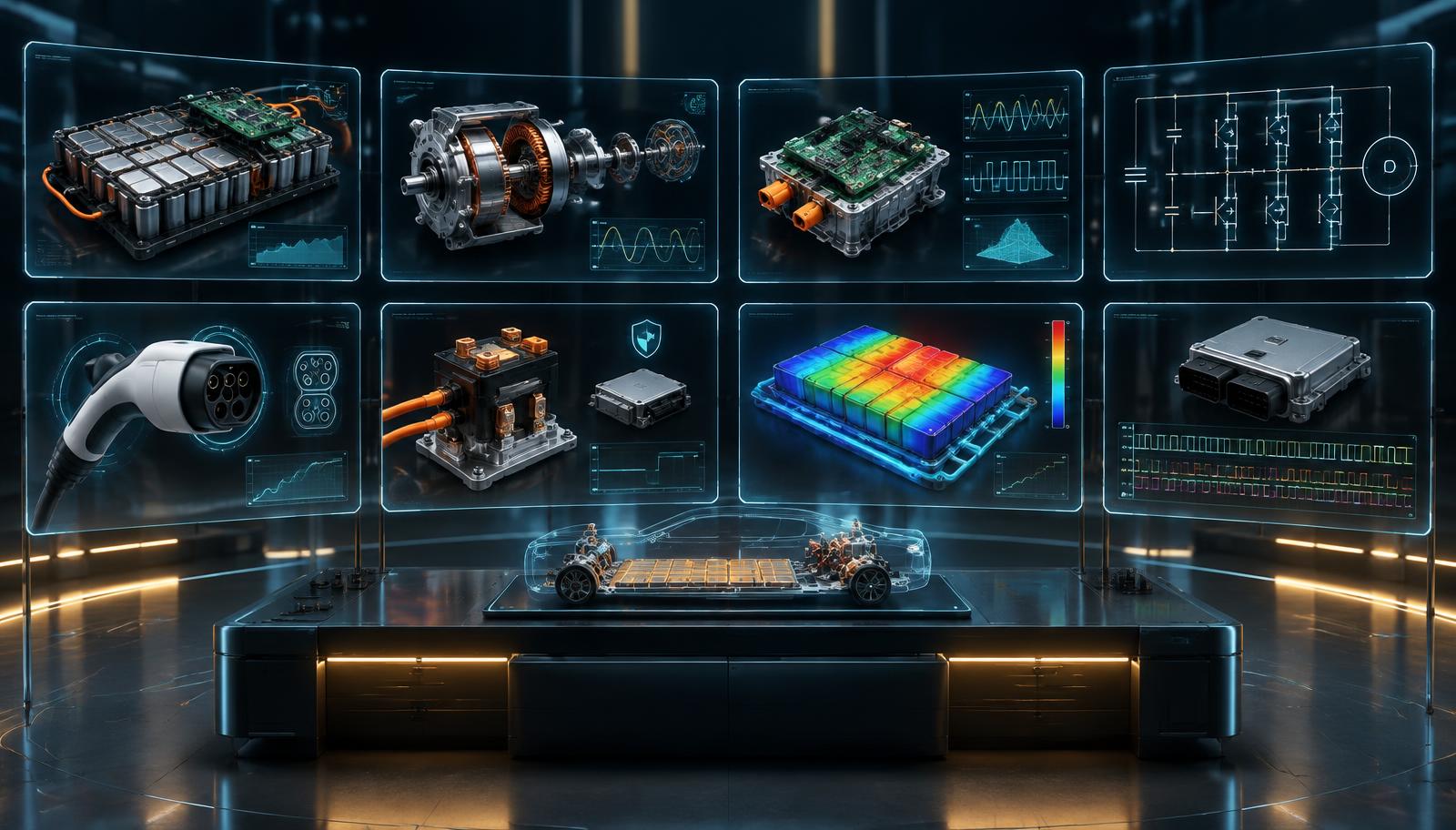
Eight holographic engineering lab panels — battery and BMS, motor, power electronics, circuits, EV charging, HV safety, battery thermal map and CAN bus — around an EV chassis

Laboratory catalogue

Eight engineering laboratories, one platform

Each laboratory focuses on one engineering domain, with its own components, instruments, controls and simulation model. All eight laboratories have live workbenches.

Find a laboratory

LAB 01Sem 5–8

Free for everyone

Battery Tech & BMS

NsMp Battery Pack Assembly & Cell Balancing

Size a 3S–16S, 1P–4P pack, wire a smart BMS, and push it until the CHG/DSG-FETs trip.
LAB 02Sem 5–8

Lab ID required

EV Powertrain & Motor Drives

BLDC / PMSM Speed-Torque & Dynamometer Mapping

Switch a 6-MOSFET inverter bridge, then drive a BLDC / PMSM motor and recover energy with regen.

LAB 03Sem 4–6

Lab ID required

Power Electronics & Solar PV

DC-DC Buck/Boost Converter — CCM vs DCM & MPPT

Tune buck, boost and buck-boost converters, then track a PV panel's maximum power point.

LAB 04Sem 1–4

Lab ID required

Basic Electrical & Analog

Thevenin / Norton Theorems & RLC Resonance

Drag-and-drop DC networks for KVL, KCL, Thevenin and Norton, plus RLC resonance sweeps.

LAB 05Sem 6–8

Lab ID required

EV Charging Protocols

IEC 61851 Control Pilot (CP/PP) & CCS2 Handshake

Step an EVSE and vehicle through IEC 61851 Control Pilot states, then run an educational CCS2 DC session.

LAB 06Sem 6–8

Lab ID required

High-Voltage Safety & Isolation

Pre-Charge Inrush Resistor Sizing & Ground Fault Analysis

Size a pre-charge resistor, sequence the contactors and find a ground fault with an insulation monitor.

LAB 07Sem 6–8

Lab ID required

Battery Thermal Management

Liquid Cold Plate vs Air Cooling — Heat Dissipation Analysis

Compare air cooling with a liquid cold plate and see how heat spreads through a battery module.

LAB 08Sem 6–8

Lab ID required

Automotive CAN & VCU

CAN 2.0B DBC Decoding & Pedal Plausibility

Build CAN 2.0A/2.0B frames, decode them with a DBC file and check dual-channel pedal plausibility.

Lab packages

Objectives, syllabus mapping and experiments

Lab 01 · Sem 5–8

Battery Tech & BMS

Free for everyone

Size a 3S–16S, 1P–4P pack, wire a smart BMS, and push it until the CHG/DSG-FETs trip.

Learning objectives

  • Configure an NsMp pack (3S–16S, 1P–4P) and verify voltage, capacity and Wh scaling with a DMM
  • Wire B−/B+, the B−…B+ sense ribbon and the P−/P+ port; diagnose miswiring from BMS fault codes
  • Compare idle, passive-bleed and no balancing as cell ΔV drifts over cycles

Syllabus mapping

  • Battery Technology & Management Systems (Professional Elective)Units II–V
  • Energy Storage SystemsUnits III–IV
  • Electric & Hybrid VehiclesUnit V — Energy storage

Experiments

  • BMS-01NsMp pack sizing, assembly & voltage verification
  • BMS-02BMS sense harness wiring & ERC fault diagnosis
  • BMS-03Passive cell balancing of an imbalanced pack
  • BMS-04OVP / UVP / OCP / OTP protection & trip timing
  • BMS-05Thermal runaway propagation in an unprotected pack

Lab 02 · Sem 5–8

EV Powertrain & Motor Drives

Lab ID required

Switch a 6-MOSFET inverter bridge, then drive a BLDC / PMSM motor and recover energy with regen.

Learning objectives

  • Drive a three-phase 6-MOSFET bridge with sinusoidal PWM and read phase voltages on a scope
  • Insert dead time and detect shoot-through faults in an inverter leg
  • Plot BLDC / PMSM speed–torque and efficiency curves and measure back-EMF

Syllabus mapping

  • Electric & Hybrid Vehicles (Professional Elective)Units II–IV
  • Electrical Machines IIUnits III, V
  • Electric DrivesUnits I–III

Experiments

  • EV-01Three-phase 6-MOSFET inverter with sinusoidal PWM
  • EV-02Dead-time insertion & shoot-through protection
  • EV-03BLDC / PMSM speed–torque & efficiency characteristics
  • EV-04Regenerative braking vs coasting energy recovery

Lab 03 · Sem 4–6

Power Electronics & Solar PV

Lab ID required

Tune buck, boost and buck-boost converters, then track a PV panel's maximum power point.

Learning objectives

  • Design buck, boost and buck-boost converters and locate the CCM / DCM boundary
  • Measure inductor-current and output-voltage ripple against the design equations
  • Trace PV I–V and P–V curves under varying irradiance and temperature

Syllabus mapping

  • Power ElectronicsUnits II–IV
  • Renewable Energy SystemsUnits II–III

Experiments

  • PE-01Buck converter — duty cycle, ripple & CCM / DCM
  • PE-02Boost converter — voltage gain & ripple
  • PE-03Buck-boost converter — inverting gain
  • PE-04PV module I–V / P–V characterisation
  • PE-05Perturb & Observe MPPT tracking

Lab 04 · Sem 1–4

Basic Electrical & Analog

Lab ID required

Drag-and-drop DC networks for KVL, KCL, Thevenin and Norton, plus RLC resonance sweeps.

Learning objectives

  • Verify KVL and KCL on a drag-and-drop DC network with virtual meters
  • Reduce a network to its Thevenin and Norton equivalents and verify the load current
  • Sweep series and parallel RLC circuits to find resonance, phase angle and Q

Syllabus mapping

  • Basic Electrical Engineering (ESC)Units I–III
  • Network Analysis & SynthesisUnits I–III

Experiments

  • BE-01Verification of KVL & KCL
  • BE-02Thevenin's theorem
  • BE-03Norton's theorem
  • BE-04Series RLC resonance
  • BE-05Parallel RLC resonance

Lab 05 · Sem 6–8

EV Charging Protocols

Lab ID required

Step an EVSE and vehicle through IEC 61851 Control Pilot states, then run an educational CCS2 DC session.

Learning objectives

  • Read Control Pilot voltage levels and PWM duty to identify EVSE states A–F
  • Relate PWM duty cycle to the advertised AC charging current and the cable's PP rating
  • Inject CP, PP and earth faults and observe the EVSE's safe shutdown

Syllabus mapping

  • Electric & Hybrid Vehicles (Professional Elective)Charging infrastructure
  • EV Charging SystemsUnits I–III

Experiments

  • CH-01Control Pilot states & PWM current advertisement
  • CH-02Proximity Pilot cable rating detection
  • CH-03Charging fault injection & safe shutdown
  • CH-04CCS2 DC charging session sequence

Lab 06 · Sem 6–8

High-Voltage Safety & Isolation

Lab ID required

Size a pre-charge resistor, sequence the contactors and find a ground fault with an insulation monitor.

Learning objectives

  • Calculate inrush current, pre-charge time and resistor energy for a DC-link capacitor
  • Sequence pre-charge and main contactors, observe the RC charging curve and the HV interlock loop
  • Discharge the DC link safely and verify the time to reach a touch-safe voltage

Syllabus mapping

  • Electric & Hybrid Vehicles (Professional Elective)HV architecture & safety
  • Power ElectronicsRC transients

Experiments

  • HV-01Pre-charge resistor sizing & DC-link RC charging
  • HV-02Main contactor sequencing & HV interlock loop
  • HV-03DC-link active discharge
  • HV-04Insulation monitoring & ground fault detection

Lab 07 · Sem 6–8

Battery Thermal Management

Lab ID required

Compare air cooling with a liquid cold plate and see how heat spreads through a battery module.

Learning objectives

  • Estimate cell heat generation from current and internal resistance
  • Compare air cooling and a liquid cold plate using a lumped thermal-resistance model
  • Observe temperature spread and hotspots across a module

Syllabus mapping

  • Battery Technology & Management SystemsThermal management
  • Heat TransferConduction & convection

Experiments

  • TH-01Cell heat generation vs C-rate
  • TH-02Air cooling vs liquid cold plate
  • TH-03Module temperature distribution & hotspots
  • TH-04Thermal propagation prevention

Lab 08 · Sem 6–8

Automotive CAN & VCU

Lab ID required

Build CAN 2.0A/2.0B frames, decode them with a DBC file and check dual-channel pedal plausibility.

Learning objectives

  • Build standard and extended CAN frames and read ID, DLC, data bytes and arbitration
  • Decode signals with DBC scaling, offset, start bit and length
  • Detect dual-channel pedal sensor mismatch and the VCU's fail-safe torque response

Syllabus mapping

  • Automotive ElectronicsIn-vehicle networks
  • Embedded SystemsSerial communication

Experiments

  • CAN-01CAN 2.0A / 2.0B frame structure & arbitration
  • CAN-02DBC signal decoding — scaling & offset
  • CAN-03Dual-channel accelerator pedal plausibility
  • CAN-04VCU fault diagnostics & fail-safe torque